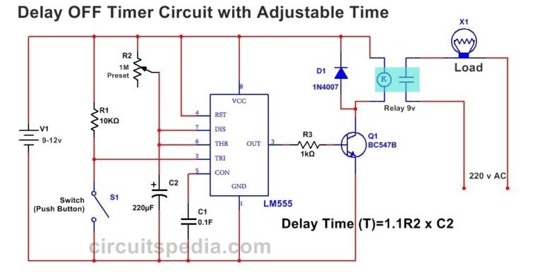
You can also use the diode to act as a snubber to prevent the relay damaging the MOSFETs at switch off. Simulate this circuit – Schematic created using CircuitLabĪt the expense of two more MOSFETs you can solve the problem. Notes 2 The earliest time-delay relays used pneumatic dash-pot motion dampers to provide the. This electronic timer circuit is helpful when you need to power On/Off any AC Appliances after a pre-defined duration. le 03132 Answer 2 A time-delay relay either waits before actuating after power-up, or waits before de-actuating after power-down.

When that is found, the relay output is asserted, and a 1 minute timer started. When idle, it waits for a signal to be asserted. switch S is opened, the delay begins again, and relay contacts R remain in. Even the cheap and tiny PIC 10F200 can do this easily. Time Delay is defined as the controlled period between the functioning of two. Your RC circuit will decay but the MOSFET will stay on. Explain what a time-delay relayis, and how it functionally diers from a regular electromechanical relay. The obvious answer is a small microcontroller, especially considering the relatively long time of 1 minute. The gate behaves more like a small capacitor so charging it up through the diode will work fine but you won't be able to discharge it.

It doesn't behave like a regular transistor whose charge will leak away through the base-emitter junction. Time range up to 10 minutes in SPDT and DPDT contact configuration. The GT3F offer true power off delay timer with 5A contacts. Both power on and momentary input trigger type SPDT and DPDT contact configuration. A timer relay is an electrical component that controls the on and off cycles of a device by using a timed switch. That was a nice try but the problem is that the MOSFET has an extremely high input impedance and a little bit of capacitance. The GT3A timer offer flexible multi-mode/multi-range timers with 5A contacts in octal plug-in format. So i thought that when i press a button, a specific capacitor discgarges and the other 2 will charge, so in order to prevent this I put the diode on the way to the gate (1 diode after each R-C combination). I put the diode there because I want to put 3 different combinations of R and C and 3 buttons in order to have 3 different time delays (30, 60, 90 seconds).


 0 kommentar(er)
